Graph Schema
This concept guide explains how to define the graph schema of a relational knowledge graph in Rel.
Introduction
A graph schema defines the nodes, edges and hyperedges of a relations, as well as the logical rules applied to them.
Defining a schema provides information about the nature of the data and describes how the data is organized.
It makes no statement about the size of the data.
In particular, it does not indicate the number of occurrences there will be for each category.
For example, if your schema has the category Company, it will not give any indication of the amount of companies in your dataset.
A graph schema can be represented by an ORM diagram. Below is an ORM diagram for a Company example. Parts of it are used throughout this guide to illustrate the concepts presented.
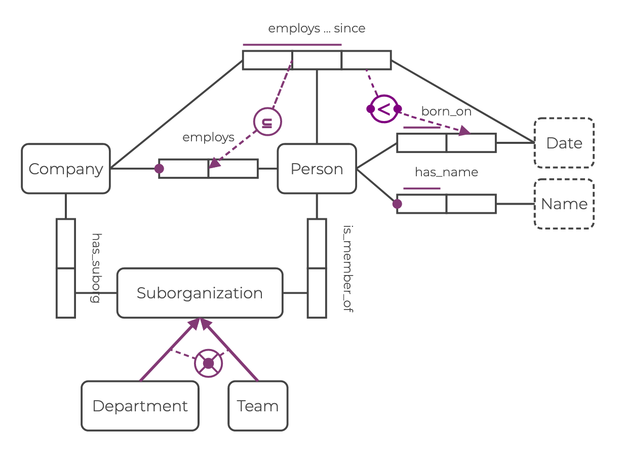
You can find the Rel code expressing the complete schema in the example section.
This guide explains the meaning of the elements in the diagram and associates Rel code to each one. See the Schema Visualization guide to learn more about ORM and LPG diagrams.
Defining the schema is a three step process, involving data types, data schema, and semantic constraints.
Step | Rel Code Example | ORM Representation |
|---|---|---|
|   | |
|  | |
|  |
Defining the Data Types
The first step in defining graph schema is to write the definitions of the data types for each node of the relational knowledge graph.
The following example shows how to do this in Rel:
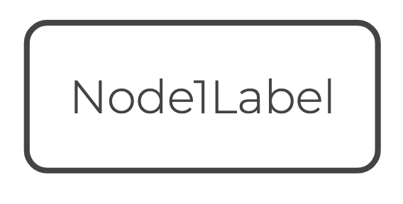
// Define an entity node.
entity type Node1Label = String
bound Node1Label = Entity
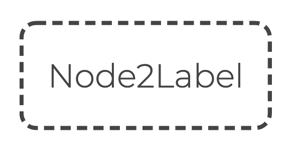
// Define a value node.
value type Node2Label = IntDefining the nodes requires entity type and value type declarations.
It is preferable to introduce a bound declaration for a relation (here Node1Label) that matches the entity name.
The purpose of this relation is to hold all the entities that have this label.
The entity type declaration defines an entity label.
This declaration does not introduce a new data type.
All entities are represented by a hash/UUID value that has the data type Entity.
In the example above, the identifying property of the Node1Label entities is a String, and the corresponding entity node (defined by the bound declaration) holds concrete instances of this entity type.
For the value node Node2Label, the value type declaration is sufficient.
It creates the constructor ^Node2Label and the corresponding type relation Node2Label, which can also act as the value node.
No bound declaration is needed.
Unlike entity types, each value type is a separate data type. See the Rel reference for details.
Both entity and value type declarations create a constructor relation, which starts with a caret ^, that will be used to populate the graph.
It is advisable to use UpperCamelCase to name entity and value types.
How to designate entity and value nodes is a decision left to the developer. More information on how to represent data using entity and value types can be found in the Graph Normal Form guide.
Following the Company example, you can express definitions of the data types for the Person and Name nodes in Rel like this:
// Entity node: `Person`
entity type Person = String
bound Person = Entity
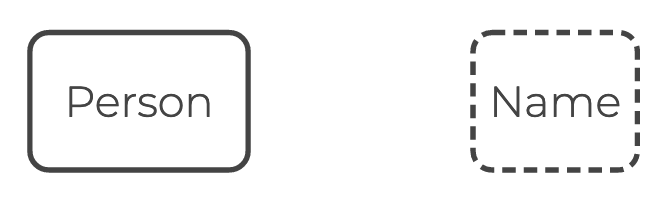
// Value node: `Name`
value type Name = StringIn ORM, entity and value nodes are represented as rounded boxes, distinguished by solid and dashed borders respectively.
Defining the Data Schema
The second step is to define the data schema of the relational knowledge graph. This will specify the data types involved in the various edge and hyperedge relations.
You can do this in Rel as follows:
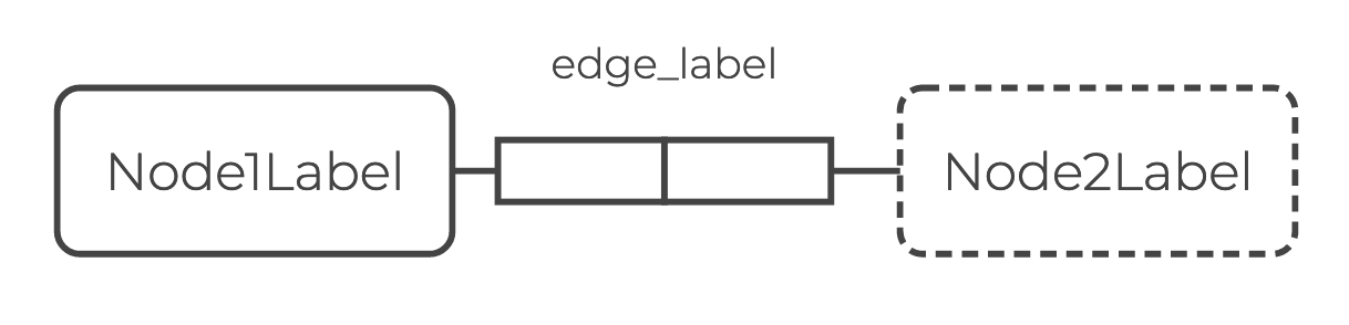
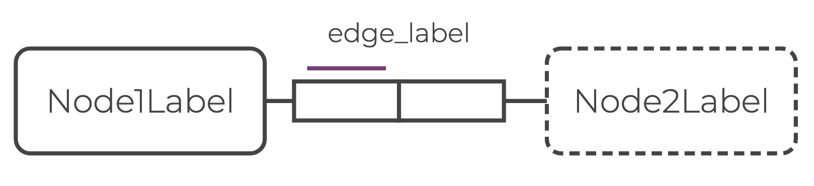
bound edge_label = Node1Label, Node2LabelThe data schemas of the relations in the relational knowledge graph are defined by bound declarations.
Bound declarations apply to relations specified on the left-hand side (here edge_label).
The right-hand side indicates the required data schema for the relation (here (Node1Label, Node2Label)).
Bound declarations generate integrity constraints (ICs), which in the case of schema rules are type constraints. Integrity constraints ensure that the data populating the graph are clean and comply with the rules stated in the schema.
It is advisable to use lowercase to name edges. Multiword labels can be linked with underscores _ (snake_case).
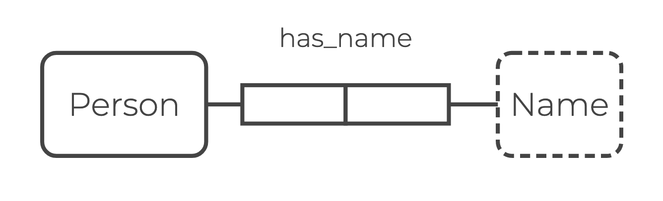
In the Company example, you can define the schema for the edge has_name, which describes the Name property of the entity Person, as follows:
// Edge: `has_name`
bound has_name = Person, Name
The bound declaration requires any relation with the name has_name to have arity 2 and contain only tuples whose first element is Person and the second is Name.
Note that in Rel the schema of hyperedges is defined straightforwardly by stating the nodes involved:
from ::std::datetime import Date

// Edge: `employs_since`
bound employs_since = Company, Person, Date
It is advantageous to represent names as values of a special value type Name and not simply as Strings.
This ensures that the property refers only to a name, and not to something else that is also represented by a String.
In ORM, edges are represented as a series of role boxes that connect two or more nodes. The number of role boxes in the diagram is the same as the arity of the edge relation. Defining schema rules is equivalent to adding role boxes between nodes.
Expressing Semantic Constraints
The third step when defining a graph schema is to express semantic constraints. You can do this by declaring integrity constraint (ICs). Here are a few commonly used constraints between nodes and edges.
In ORM, semantic constraints are represented by purple icons.
Constraints Between Nodes
Some semantic constraints, such as mandatory role, functional dependency, and subtype constraints, apply to the connection between nodes.
Mandatory Role Constraints
You can express mandatory role constraints in Rel as follows:
ic a_must_have_b(a) {
    A(a)
    implies
    exists(b: B(b) and edge_x(a, b))
}This IC means ”A has at least one B“.
Those nodes are linked by an edge in edge_x.
Following the Company example, you can express the mandatory role constraint “A Person has at least one Name” in Rel like this:
ic person_must_have_name(pers) {
    Person(pers)
    implies
    exists(name: Name(name) and has_name(pers, name))
}
In ORM, a mandatory role constraint is illustrated by a large dot on the role box connector.

Functional Dependency Constraints
A functional dependency constraint is a uniqueness constraint that expresses a many-to-one connection. Here is how to express it in Rel:
ic A_has_one_B(a, b1, b2) {
    edge_x(a, b1) and edge_x(a, b2)
    implies
    b1 = b2
}This IC means ”A has at most one B“.
It is also possible the write this IC using the built-in relation function:
ic edge_x_is_a_function {
    function(edge_x)
}
This will check that the initial element A of the tuple in the relation edge_x maps to only one value for each B.
Following the Company example, you can express the mandatory role constraint “A Person has at most one Name” in Rel like this:
ic person_has_one_name(pers, name1, name2) {
    has_name(pers, name1) and has_name(pers, name2)
    implies
    name1 = name2
}Combining a mandatory and a functional dependency constraint expresses that a Person has exactly one Name.
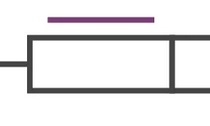
In ORM, a functional dependency constraint is illustrated by a purple bar above the first role box.
Exclusive-or Subtype Constraints
You can use the keyword xor to express exclusive or subtype constraints in Rel, as shown in the following example:
ic xor_subtype(x) {
    Supertype(x)
    implies
    Subtype1(x) xor Subtype2(x)
}This IC means ”Subtype1 and Subtype2 are mutually exclusive”.
Following the Company example, you can express the exclusive or subtype constraint ”Team and Department are mutually exclusive” like this:
ic xor_suborg(x) {
    Suborganization(x)
    implies
    Department(x) xor Team(x)
}
In ORM, an exclusive or subtype constraint is illustrated by a dot over an “X” in a large circle.
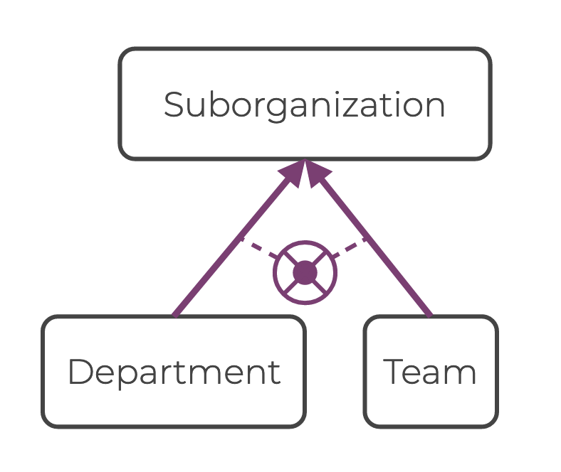
The subtype symbol above is linked to purple arrows. A purple arrow links two nodes that have a subtype relation.
Constraints Between Edges
Constraints can also involve multiple edge relations, allowing you to express more complex dependencies. Common examples are value-comparison and subset constraints, which are discussed in more detail below.
Value-Comparison Constraints
The following example shows how to express value-comparison constraints in Rel:
ic edge_x_sup_edge_y(a, b1, b2) {
    edge_x(a, b1) and edge_y(a, b2)
    implies
    b1 > b2
}This IC means “the value of B for edge_x is superior to the value of B for edge_y“.
Following the Company example, you can express the value-comparison constraint “A Person must be employed_since a date that is more recent than the date they were born, born_on” in Rel as follows:
ic employs_since_sup_born_on(pers, dt1, dt2) {
    employs_since(pers, dt1) and born_on(pers, dt2)
    implies
    dt1 > dt2
}
In ORM, a value-comparison constraint is illustrated by a comparison operator in a large circle.
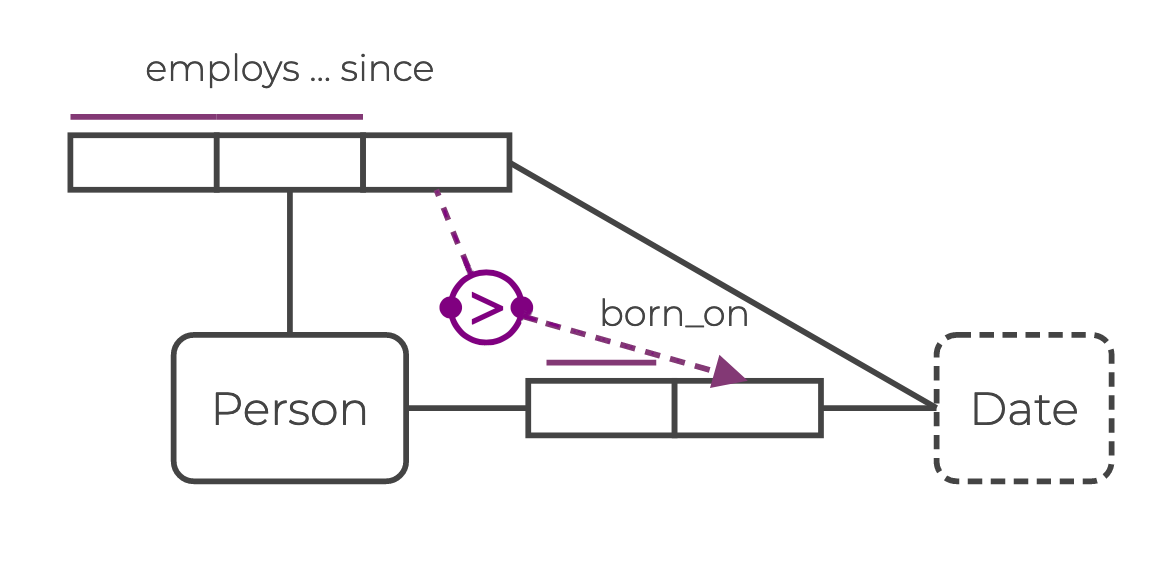
The value-comparison arrow starts and points to role boxes on the same side of the edges the constraint imposes on.
Subset Constraints
The following example shows how to express subset constraints in Rel:
ic edge_y_subset_edge_x(a, b) {
    edge_y(a, b)
    implies edge_x(a, b)
}This IC means “every pair (a, b) in edge_y is also a pair in edge_x“.
Following the Company example, you can express the subset constraint “A Person who has been employed_since a Date at a Company is a Person employed at that Company” in Rel like this:
ic emp_since_sub_employs(comp, pers) {
  employs_since(comp, pers, _)
  implies employs(comp, pers)
}
The underscore (_) indicates that the last element of the tuple for employs_since may contain any value.
The expression inside the braces effectively means “the set of pairs from the first two columns of employs_since is a subset of the set of pairs in employs.”
A subset constraint is symbolized by a ⊆ symbol in a large circle.
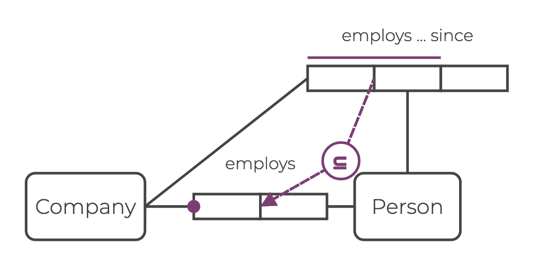
The subset arrows goes from and to a junction of two role boxes. This shows that the constraint is on that pair of nodes.
Example
The ORM diagram below represents the complete schema for the Company example.
In order to express this schema in Rel, follow the steps presented at the beginning of this guide.
The schema is expressed within a module called CompanyGraph.
First you define the data types for the value node Name and the entity nodes Company, Person, Suborganization, Department, and Team.
Note that the value node Date is not defined at this stage.
This is because Date is a Rel data type.
Next you define the data schema for the hyperedge employs_since and the edges has_name, born_on, is_member_of, employs, and has_suborg.
Finally, you express the semantic constraints between nodes and between edges.
// model

module CompanyGraph
    from ::std::datetime import Date

    // STEP 1 - Data types of nodes
    // Entity nodes
    entity type Company = String
    bound Company = Entity

    entity type Person = String
    bound Person = Entity

    entity type Suborganization = String
    bound Suborganization = Entity

    entity type Department = String
    bound Department = Entity

    entity type Team = String
    bound Team = Entity

    // Value nodes
    value type Name = String

    // STEP 2 - Data schema of edges and hyperedges
    // Edge / Node attribute
    bound has_name = Person, Name

    bound born_on = Person, Date

    bound is_member_of = Person, Suborganization

    bound employs = Company, Person

    bound has_suborg = Company, Suborganization

    // Hyperedge / Edge attribute
    bound employs_since = Company, Person, Date

    // STEP 3 - Semantic constraints
    // Mandatory constraints
    ic company_must_have_person(comp) {
        Company(comp)
        implies
        exists(pers: Person(pers) and employs(comp, pers))
    }

    ic person_must_have_name(pers) {
        Person(pers)
        implies
        exists(name: Name(name) and has_name(pers, name))
    }

    // Functional dependency constraints
    ic person_has_one_name(pers, name1, name2) {
        has_name(pers, name1) and has_name(pers, name2)
        implies
        name1 = name2
    }

    ic person_has_one_DOB(pers, dt1, dt2) {
        born_on(pers, dt1) and born_on(pers, dt2)
        implies
        dt1 = dt2
    }

    ic company_person_has_one_hiring_date(comp, pers, dt1, dt2) {
        employs_since(comp, pers, dt1) and employs_since(comp, pers, dt2)
        implies
        dt1 = dt2
    }

    // Exclusive or subtype constraint
    ic team_dept_exclor(x) {
       Suborganization(x)
       implies
       Team(x) xor Department(x)
    }

    // Value-comparisons constraint
    ic employs_since_sup_born_on(comp, pers, dt1, dt2) {
        employs_since(comp, pers, dt1) and born_on(pers, dt2)
        implies
        dt1 > dt2
    }

    // Subset constraint
    ic emp_since_sub_employs(comp, pers) {
        employs_since(comp, pers, _)
        implies employs(comp, pers)
    }

end
Summary
Defining the schema of a relational knowledge graph involves three steps:
- Define the data types for the entity and value nodes of the relational knowledge graph.
- Define the schema rules creating the edges and hyperedges of the relational knowledge graph.
- Express logical constraints between nodes and between edges.
See Also
See Schema Visualization for details on ORM diagrams and how they compare to LPG diagrams. See Elements of a Relational Knowledge Graph to learn more about how to define nodes, edges, and hyperedges in Rel. It also provides a small example of how to build and query a relational knowledge graph. See also My First Knowledge Graph and The Lehigh University Benchmark for more examples.